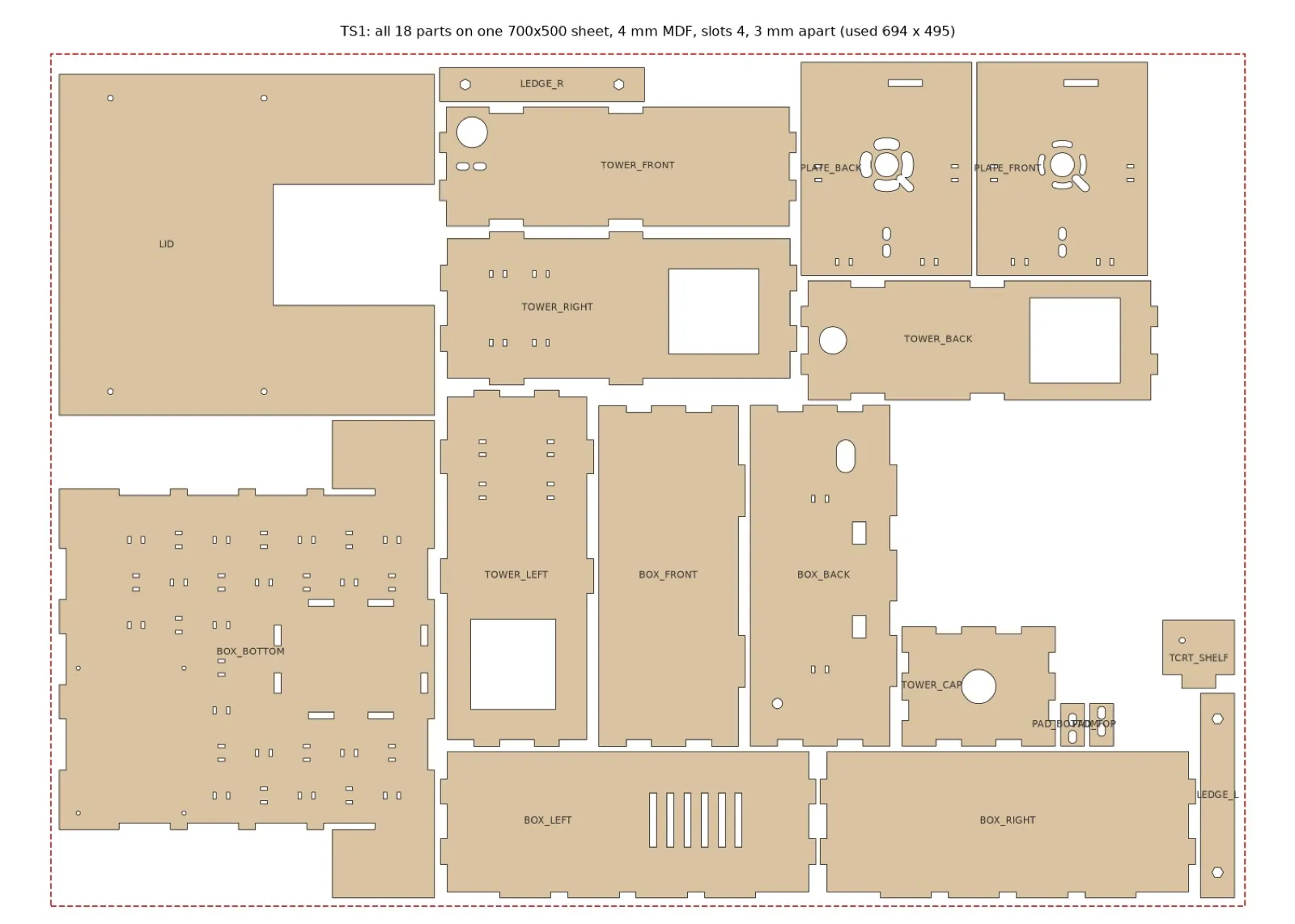
TS1 thrust stand
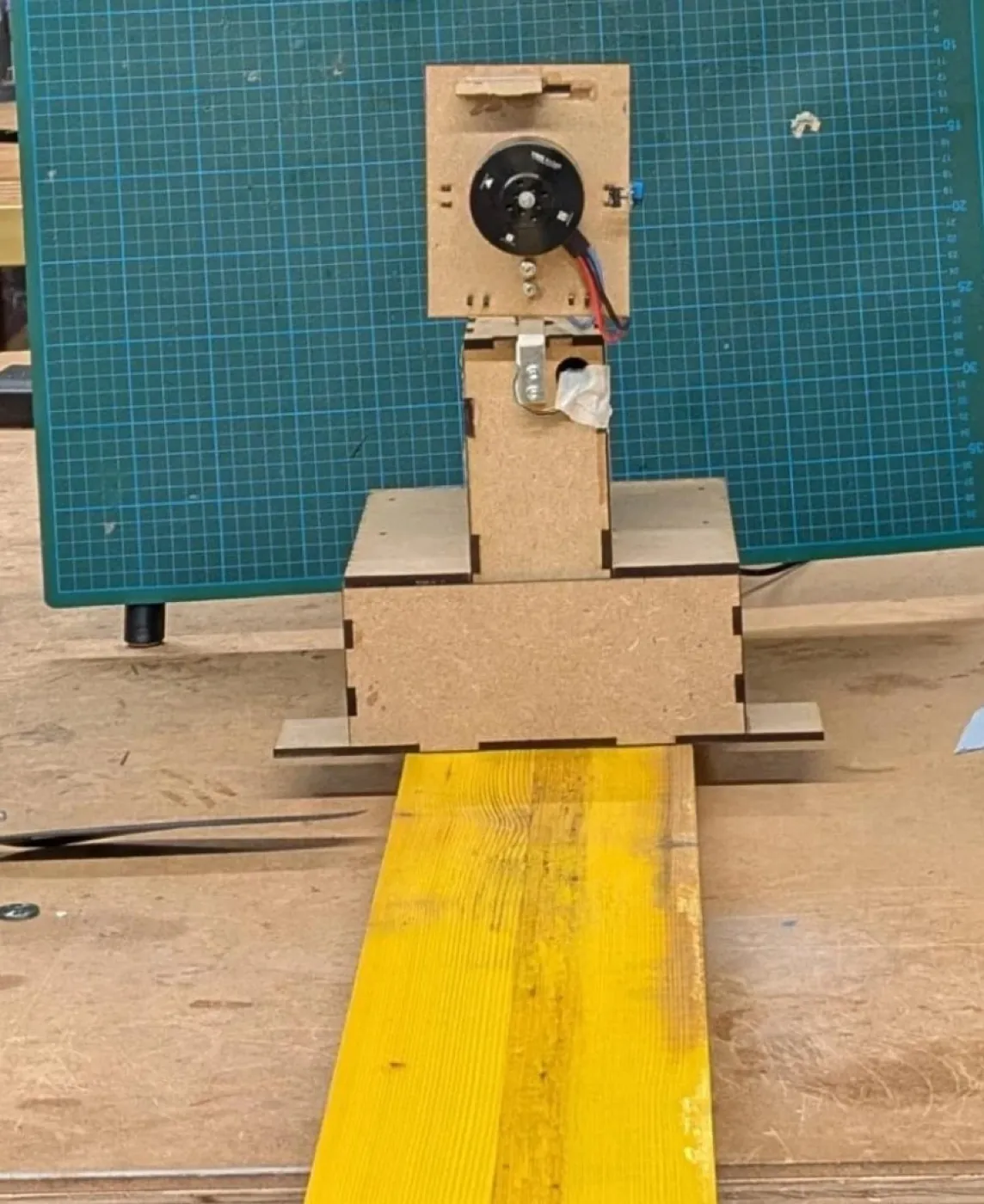
Before P8N flies we want to know what its motors and props actually do. TS1 is a stand we cut from MDF on a laser cutter and built ourselves. One motor pushes against a load cell while an ESP32 logs thrust, rpm, temperatures, voltage and current, and a Python dashboard on the laptop controls it.
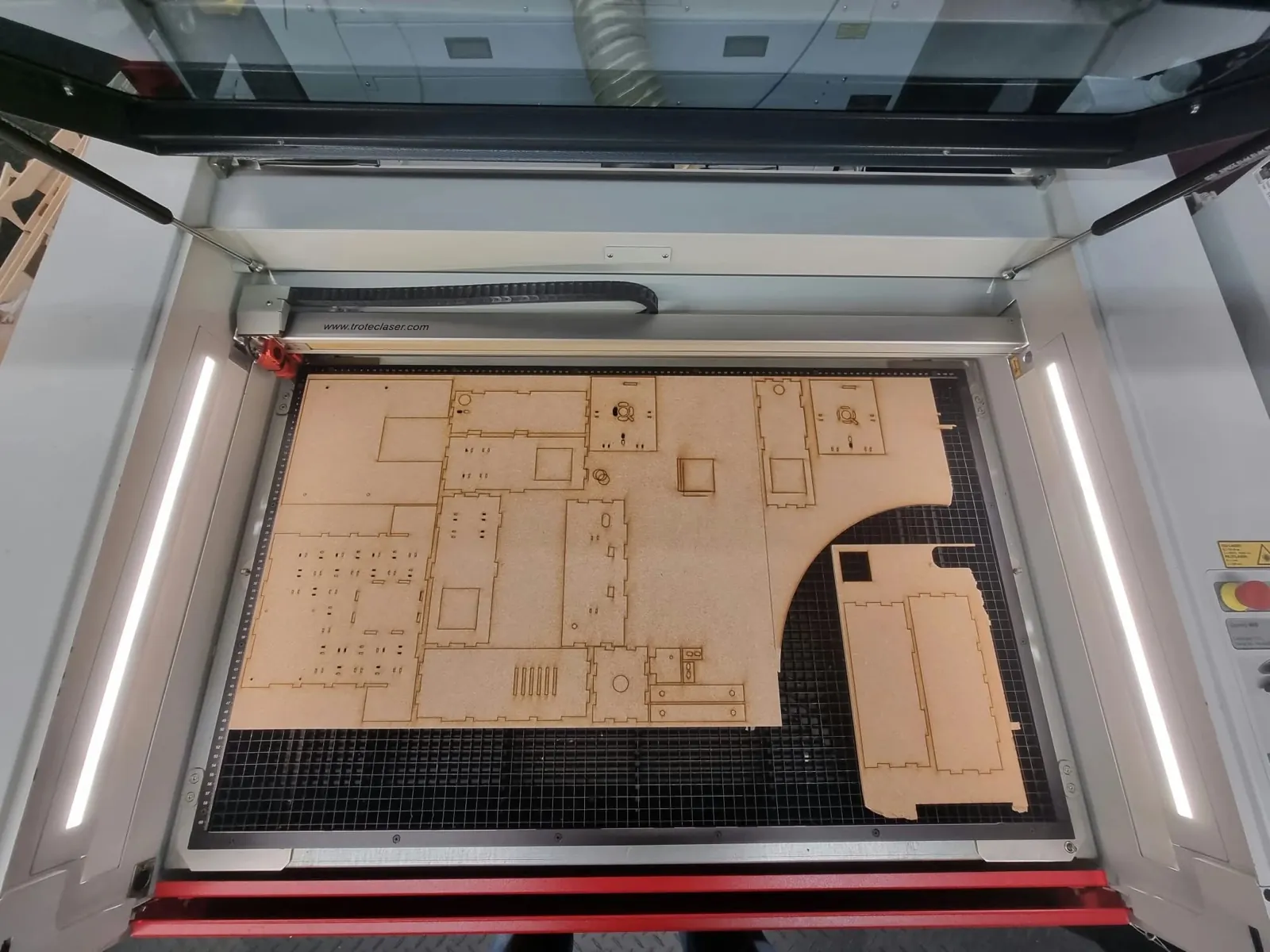
All 18 parts on the laser cutter
The parts are generated from the design file, together with a 3D model and clash checks, so a change in one dimension changes every part that touches it.
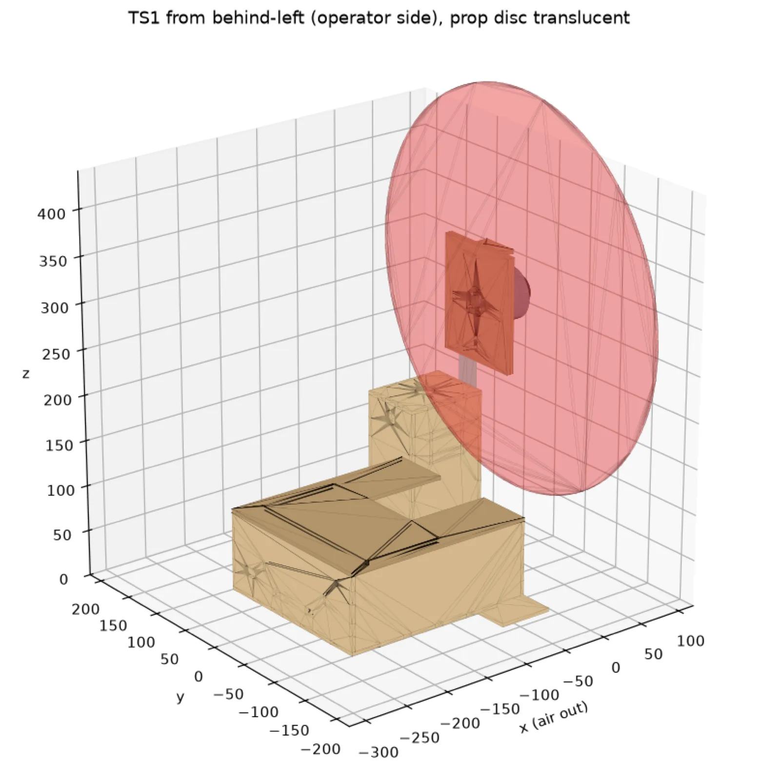
The CAD view
What works
- The ESP32 controls the motor speed controller, with a watchdog: if the laptop stops talking, the motor cuts within about half a second.
- rpm from an optical sensor and a white mark on the motor bell, within about 1% of the motor's own count.
- Thrust from the load cell, with 0.4 g of noise.
- Two temperature sensors, one on the speed controller and one on the motor.
- First runs with props on, at low throttle: 12 g to 76 g of thrust.
What I did
I built the stand together with Davide: the test cut, laser-cutting the parts, the recut when the laser stopped, and the assembly and wiring. Then I took over the electronics. I added a second temperature bus and fixed the firmware watchdog and a timing bug in the dashboard's tests. Now I'm working on the open problem: the current sensor reads wrong.
Still open
Current measurement, the first logged run, calibrating thrust with weighed masses, then full battery voltage.
Work log · 8 steps
-
The current sensor
The current reading sticks at 0.5 A. I listed the possible causes, checked each with a multimeter, and lined up a replacement sensor in case the original is faulty.
-
First props-on runs
Low-throttle runs at 6S with the P8N motor and prop. 12 g to 76 g of thrust.
Learned: The prop for the other spin direction gave negative thrust.
-
Second temperature bus and firmware fixes
Added a second temperature-sensor bus, fixed the firmware watchdog and a timing bug in the dashboard's tests.
-
Wiring and soldering
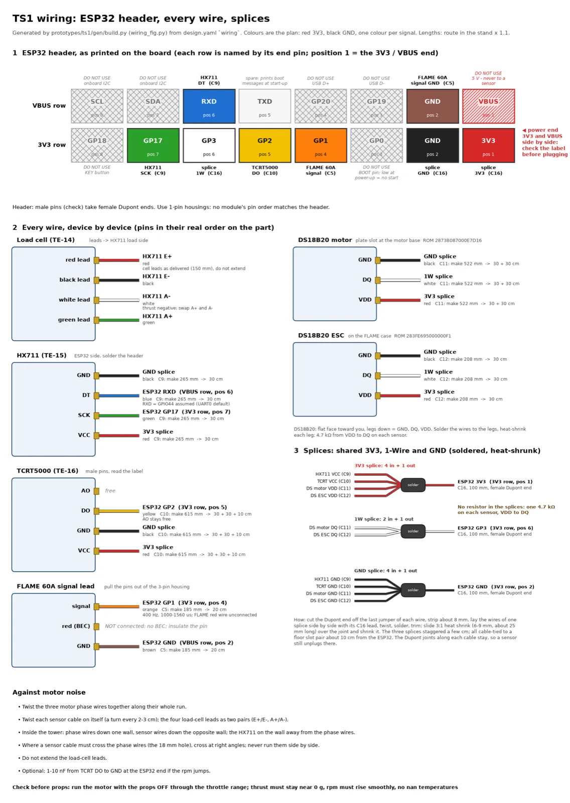
Wired the ESP32, ESC, Pixhawk and sensors, and soldered three splices for power, ground and the temperature bus instead of using a stripboard.
-
Assembly
Sanded and glued the flat-pack parts, laminated the motor plate, mounted the motor, load cell, rpm shelf and electronics box, following our own step-by-step procedure.
Learned: Sanding changes the thickness, so screw lengths had to be checked again for every 4 or 5 mm part.
-
Cutting the stand
Davide and I cut all 18 parts from MDF on a Trotec laser cutter. The laser stopped partway, so we split the remaining 10 parts into their own files and recut them.
Learned: Plan a cut so that you can restart it. Moving the job in the laser software did not work; separate files did.
-
Test cut for the slot fit
A small test piece with slots at three widths, holes for M2 to M4 screws and a nut pocket, cut before the full sheet.
Learned: The 4.0 mm slot fit 4 mm MDF best, so we set the clearance to zero. A cheap test cut saves a whole sheet.
-
Parts generated from one design file
All laser-cut parts as DXF files, a 3D model, clash checks, a parts list and a wiring sheet, nested on one 700 × 500 mm sheet.
Learned: When the parts come from one file, changing the sheet thickness changes every slot at once.